A major challenge in transitioning to a hub-motor system was designing a cooling sleeve that could remove enough heat, fit cleanly within the wheel hub and suspension assembly, and withstand the high temperatures and harsh environmental conditions at the wheel. I took on this project with the goal of maximizing reliability, heat transfer from the motor to the coolant, and minimizing production costs due to some financial hardships our team was under.
Goals
Evaluating Manufacturing Routes
- Maximize heat transfer between the motor and coolant
- Minimize pressure drop across the cooling sleeve
- Minimize production cost and time
- Minimize additional unsprung mass at the wheel
- Maintain leak-free performance over an endurance event
Starting, I knew that other FSAE teams had successfully used metal additive manufacturing to produce cooling sleeves with complex internal channels. While this route achieves excellent thermal and structural performance, it is expensive and has long turnaround times.
I explored alternative manufacturing paths that maintained similar design freedom but lowered cost and build complexity. Three primary candidates were:
- Resin-based SLA printing
- Nylon 12 SLS printing
- Aluminum Investment Casting
SLA Resin Results
Fortunately, our team was sponsored a resin 3D printer, which allowed rapid experimentation with different geometry sleeve prototypes. Initial prints were dimensionally accurate and water-tight, making them great for rapid iteration.
The following limitations of the resin sleeves were found after long-term water exposure:
- SLA resin is hygroscopic and has poor hydrolytic stability
- Water and heat exposure significantly degrade even ‘tough’ resin
- Parts of the sleeve were too brittle and prone to fatigue failure
- Resin printing limited certain sleeve geometries
Since the car wasn’t working at the time, full thermal cycling tests weren’t something I could do, but based on the other shortcomings of the resin sleeves, long-term reliability was definitely going to be an issue.


Nylon SLS Results
SLS Nylon 12 offered significantly better toughness and thermal resilience. The design freedom of SLS also reduced constraints on overhangs and internal channel features. If needed, using glass bead-filled Nylon or carbon fiber Nylon was also an option for even greater strength and thermal resilience.
Although Nylon was promising, there were still two main issues:
- Nylon is also Hygroscopic
- SLS prints are naturally too porous to be water-tight
This issue was solved by applying an epoxy layer over the entire sleeve to fill in the pores. Compared to SLA, this option was more robust, and the long-term durability of the sleeve was more promising.
")
")
Investment Casting Plans
Although Nylon SLS seems promising, there are still concerns about how well or how long the sleeve will hold up after prolonged water exposure and significant thermal cycling. Another concern is the thermal expansion of the sleeve. Since Nylon has a low thermal conductivity, I designed the sleeve so the water contacts the motor directly and is held inside with an o-ring seal. The possibility of losing seal compression, especially after many rounds of thermal cycling, is a major concern.
Having an aluminum sleeve would eliminate most risk since its CTE is very close to the motor housing. It is naturally much stronger and has greater fatigue strength.
My plan going forward is to use one of our university’s casting facilities to make a lost-filament investment cast sleeve. The idea is to print the geometry using Polycast burnout filament, dip it into a ceramic slurry, burn out the filament, and pour aluminum into the ceramic mold. This lets us create complex internal cooling channels quickly, cheaply, and with a strong and reliable final part.
Although aluminum casting is promising, a few key concerns include:
- Cast porosity
- Post-processing requirements
- Fine geometry quality
- Added weight
Fortunately, I’ve gotten to meet with very knowledgeable people, and with specific casting processes, a machine shop available to me, and alloys available at my university, this is looking like a strong future option.
Thermal Design Approach
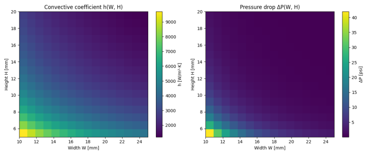
To design the sleeve, I wanted to maximize the overall heat transfer coefficient between the motor and the water. This meant maximizing the convective coefficient and eliminating any conductive resistance to heat flow.
To evaluate channel geometries, I got to use what I’d learned in my heat transfer class and developed a Python-based thermal and pressure drop simulation. The program swept different channel heights and widths and calculated the resulting convective heat transfer coefficient and pressure drop.
Based on previous pressure testing and our system’s pump curve, I was aiming to keep the pressure drop below ~ 35 kPa.
The calculator made necessary assumptions and approximations, so the goal was to get a good starting point and then move towards CFD physical validation.
The graphs show the relationships between the convective coefficient and pressure drop for different channel heights and widths, with an optimal design being our maximum convective heat transfer under a 35 kPa pressure drop (5 psi).

After identifying a good starting point, channel geometry. I moved the CAD to STAR CCM+ to try to validate my initial calculations through CFD. I had never done CFD before, but fortunately, my team had a lot of experienced aero members who were able to help get me started while I adapted their knowledge to a heat transfer-focused simulation.

The resulting values I got from the CFD were quite different than what I had calculated, which wasn’t too surprising; however, the trend between different channel geometries stayed consistent, giving me confidence in moving forward with the optimal geometry calculated in the Python simulation.
Future Plans
Manufacturing Finalization
As I move toward a finalized design, I’ll be wrapping up testing on the different manufacturing methods. Once I know which approach is the most reliable and feasible, I can lock in the final sleeve geometry and as well as other external features like mounting and sealing details. Ideally, the aluminum casting process performs well since it’s fast and inexpensive.
I also recently found out that there’s a Titanium SLM metal printer on campus, which opens up a pretty exciting option for a long-term, premium version of the sleeve. A titanium-printed part would be extremely tough, lightweight, and thermally stable under cycling, which would be great.
Physical Testing
After mostly completing the design and having some prototypes manufactured, the next step is testing and physical validation. Unfortunately, due to a financial block on our team and other issues with the car limiting us, I haven’t been able to move forward with this much, but test plans include:
- Pressure drop validation / Sealing capabilities
- This has been completed since we already have pressure transducers
- Heat transfer validation / Thermal cycle testing
- We are developing a motor simulator using cartridge heaters inside of an aluminum housing and inline coolant thermistors to test how much heat is extracted from the ‘motor’ and how well the sleeves hold up after thermal cycling.
- On car testing
- Once the new car starts running, testing the cooling sleeves throughout mock endurance events will be crucial in validating their performance and reliability.

Contact
Please feel free to contact me through the following links!