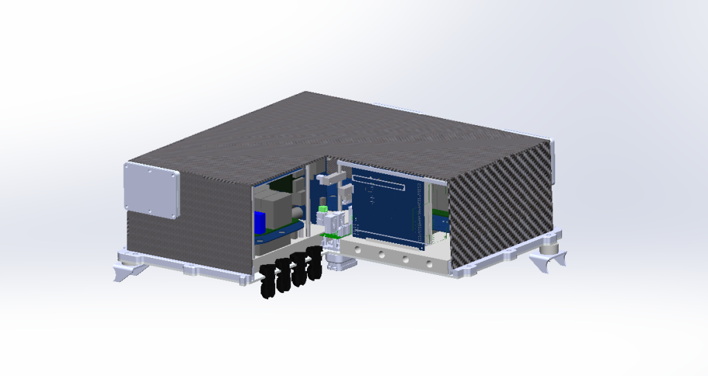
For the 2024-2025 season, we moved from a 2-motor RWD system to a 4WD in-hub system. One of my projects related to this revamp was developing an enclosure for the new power inverters, which were supplied without any protective housing.
I contributed to the design and took the lead on manufacturing the enclosure. Our objective was to create a lightweight, compact, and IP56-rated solution. The project not only tested my design abilities but also gave me the opportunity to apply my manufacturing experience and build new, practical skills.
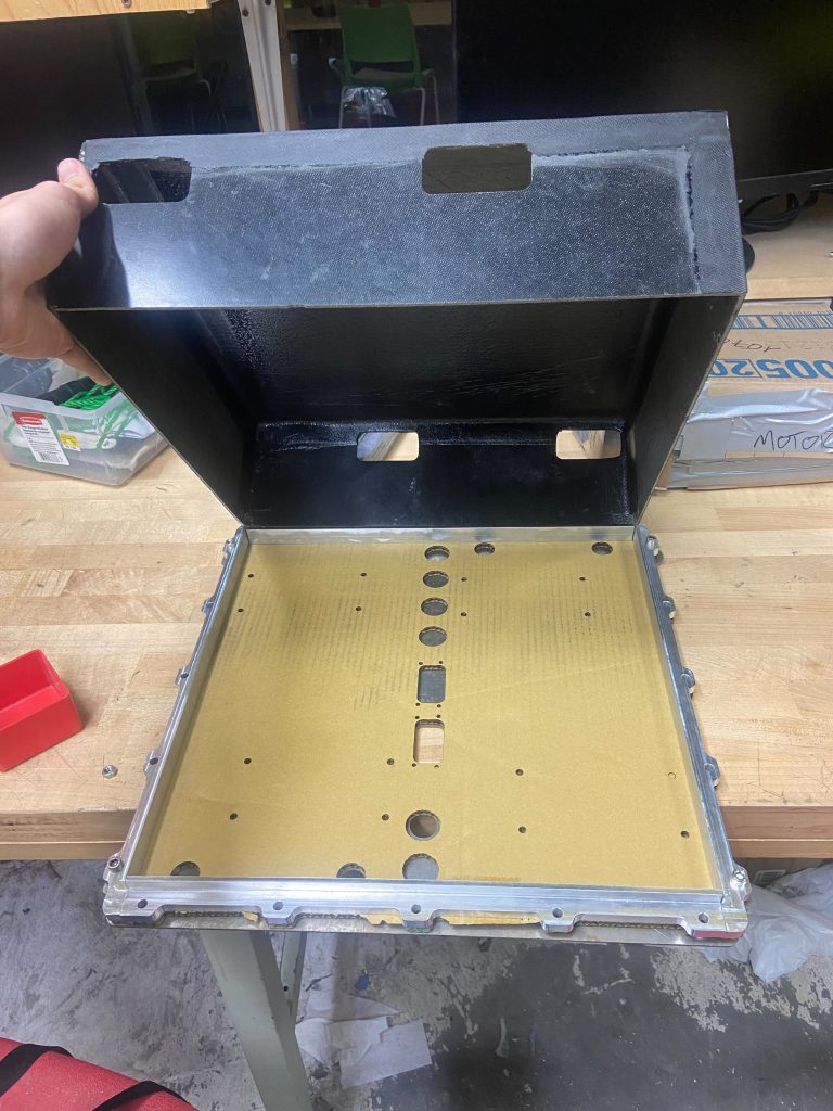
The lid was developed with a 1/16″ foam core center and a pre-preg carbon fiber + fiberglass layer on each side to be as thin as possible while maintaining structural integrity.
Manufacturing accuracy of the lid was crucial since the available clearance between the chassis, enclosure lid, and inverter all added up to less than 1mm in the CAD.
The lid was waterjetted into different sections, and a custom waterjetted mold allowed us to ensure accuracy of the top edges of the lid, and a 1-degree draft angle gave us the clearance on the bottom required for the inverter base.
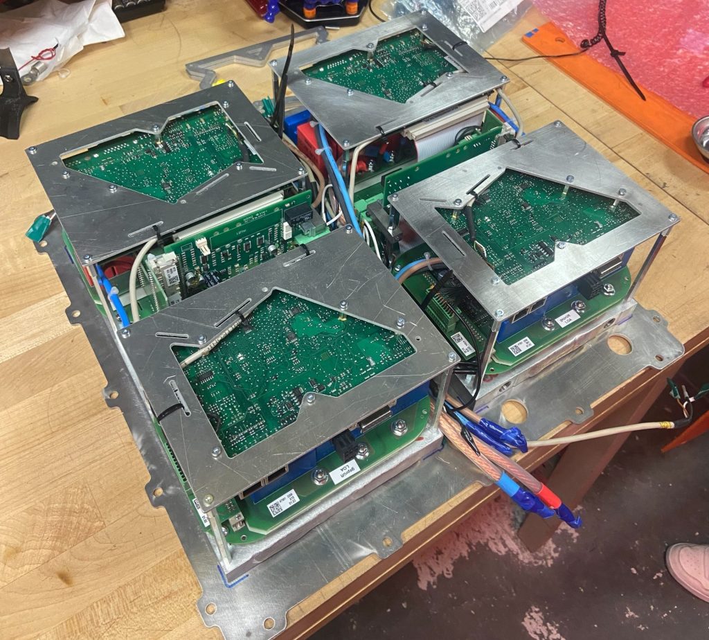
Lots of measurements, test fits, and some last-minute modifications of the stock inverter guards gave us just the fit we needed.
CF Lid Layup Mold
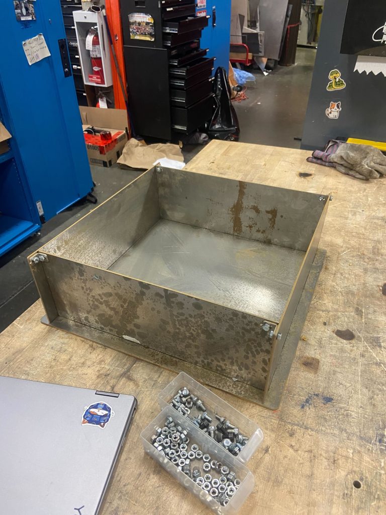
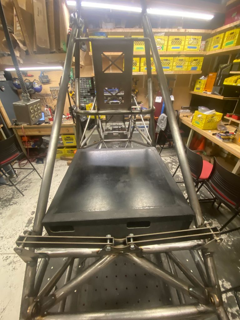
Enclosure Test Fit With Chassis
Test Fit Over Laser Cut Cardboard Base
Lid Mounting Brackets & Sealing
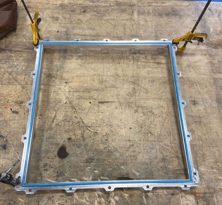
The highest risk of water ingress was at the lid-to-base connection, where the inverters were mounted. With tight packaging constraints both at the top and bottom of the enclosure, we developed a custom seal and CNC-machined brackets featuring a seal groove and precise mounting points between the lid, base, and chassis.
The lid brackets were machined separately and utilized a slot feature to mate the brackets together and allow for them to be easily and accurately epoxied together.
Unfortunately, our CNC machine was broken, so a team member was able to machine these at their workplace, but I got a chance to make them myself afterwards.
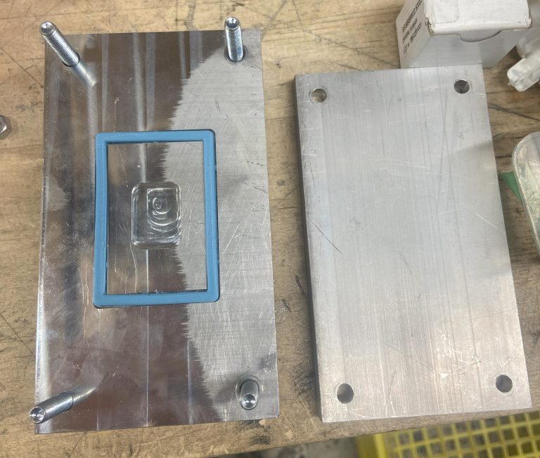
The custom seal was developed by a first-year student on my subteam, and I learned lots about custom gaskets while helping.
This seal was developed using a number of 3D printed mold segments and was tested using other milled grooves in smaller test pieces.
Bonding Sealing Brackets Together
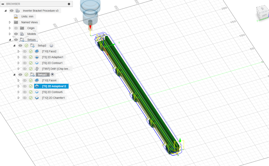
Fusion CAM For Bracket Machining
Custom Seal Test Piece
Access panels and Final Touches
The base plate was waterjetted with slots and holes for all the inverter mounting points, electrical connections, and cooling loop access points. With packaging constraints being the main trend in this design, fitting 6 large cable glands, 2 amp seals and 4 cooling line fittings out of the bottom of the enclosure required a lot of adjustment, further sealing design and involvement with the HV electrical team.
To allow access to connection ports for software to work on the inverters, we also had access panels that could be opened when needed. These were CNC-machined with an o-ring seal groove and then epoxied onto the inverter lid.
Finally, a Faraday cage was installed on the inside of the lid, and the enclosure was given a shower to ensure everything was waterproof.
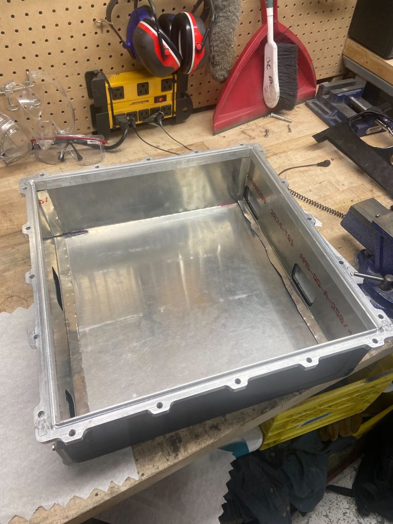
Installed Aluminum Faraday Cage
Inverter Test Fit
Overall, this project was painful yet enjoyable, and took a lot of planning and cross team colaboration to work out. It taught me about different manufacturing methods including composites work, CNC machining, and custom seal development and gave me greater insight into the challenges and potential solutions of integration and packaging problems.
Contact
Please feel free to contact me through the following links!