For the 2024 – 2025 season, one of my projects was the design of a new cooling system for our car. This year, we transitioned from a 2-motor RWD system to a 4WD in-hub motor system. This meant a complete revamp of the previous cooling system and a generous amount of design and integration challenges.
This project developed my skills in Python simulation, design and planning of physical test rigs, calculated component selection, heat transfer and fluid dynamics, and gave me a chance to learn a lot about and work with members from different sub-systems of the car.
Thermal Simulation
Designing around our new motors and inverters was challenging since we had no means of conducting physical testing on them yet and had almost no data to carry on from previous years. There was also little to no thermal or efficiency data on the motors, except for maximum temperature requirements.
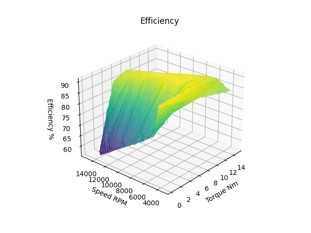
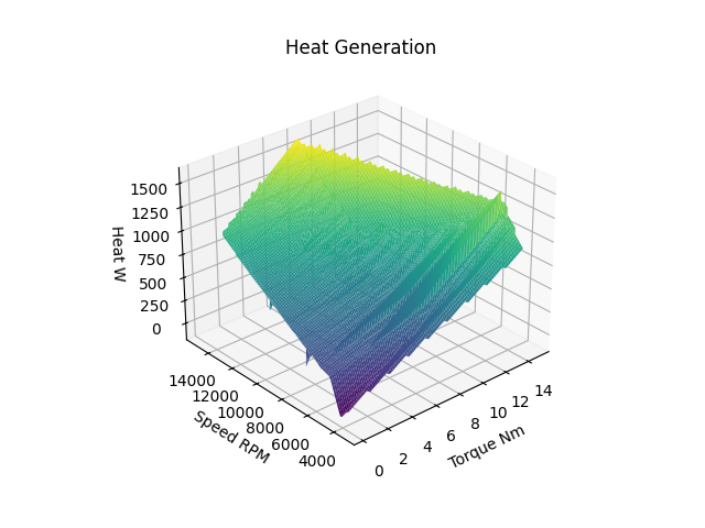
To determine our heat rejection requirements, I wrote a Python script that took data from a previously developed lap simulation where I was able to extract voltage and current values to determine motor input power, as well as output speed and torque to calculate output power. From there, I assumed all losses were converted to heat and was able to develop an efficiency map and get an average heat generation value for an endurance event.
Final calculations revealed our system was generating an average of 3.2 kW at 80.9% efficiency throughout an endurance lap.
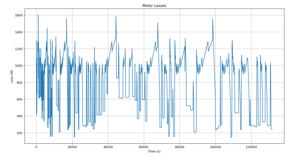
Single Motor Loss Data
System Configuration
Determining the configuration of the cooling loop was a new and unique challenge, driven by the increased number of components and the need for the loop to span the full length of the car.
My primary goals in the layout were reliability, minimized weight and complexity, and prioritizing cooling for the sensitive power electronics. An additional challenge that arose after pump selection was determining optimal pump placement within the loop to maintain consistent pressure and reduce the risk of cavitation.
I evaluated several loop configurations, including parallel cooling sections and split loops, but ultimately selected a single series loop. This configuration offered the greatest reliability, with a lower risk of localized hotspots causing overheating, while also minimizing system complexity and mass compared to alternative layouts.
Although this was the best option for the current design, future iterations should investigate parallel cooling to improve thermal distribution and reduce pressure drop, which I discuss further in the pump selection section of this overview.
Proposed Loop Configuration
Radiator Selection
Radiator Wind Tunnel Testing
To select an appropriately sized radiator, I initially attempted to develop an iterative Python program that would estimate the minimum required radiator size across an endurance event using the NTU method. However, this approach proved impractical due to the limited availability of thermal performance data for small radiators. The large number of assumptions required for radiator characteristics, combined with environmental uncertainties, made the model unreliable.
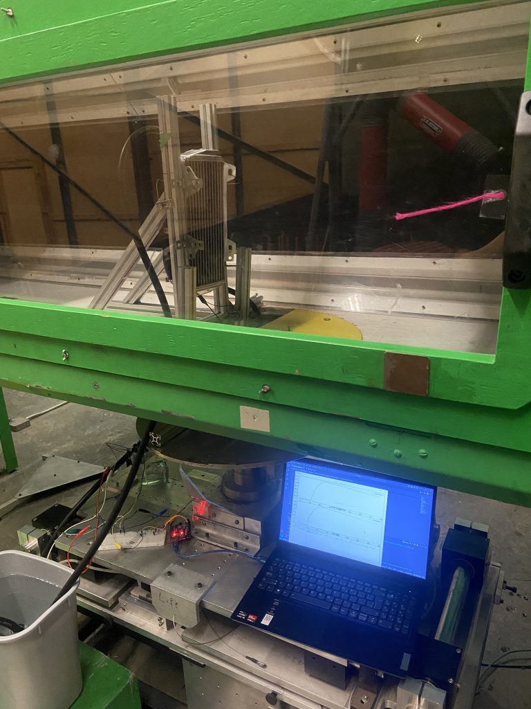
To combat this issue, I shifted focus to physical testing, which provided more meaningful results. Fortunately, our school has access to a small wind tunnel, where I set up a test rig to evaluate different radiator sizes under varying airflow conditions.
From the testing, I identified radiator size and airflow combinations capable of meeting our cooling requirements. Based on these results, I selected an appropriate radiator and designed a fan shroud to ensure stable airflow, enabling the system to consistently maintain target operating temperatures.
Pump Selection
To properly spec a pump for the cooling loop, the first step was to determine the system pressure drop at the required flow rate. To measure pressure drop, I guided a new team member through setting up a test system to use pressure transducers to measure pressure drops across each component. The results were compiled into a spreadsheet, where additional system pressure losses were calculated to estimate the total system pressure drop.
In the end, we determined the pressure drop across the system to be ~90 PSI, which was much higher than expected. This was because the current design for our custom motor cooling sleeves introduced a very high pressure drop, but just in case this remained, we had to spec pumps that could comfortably achieve the required flow rate.
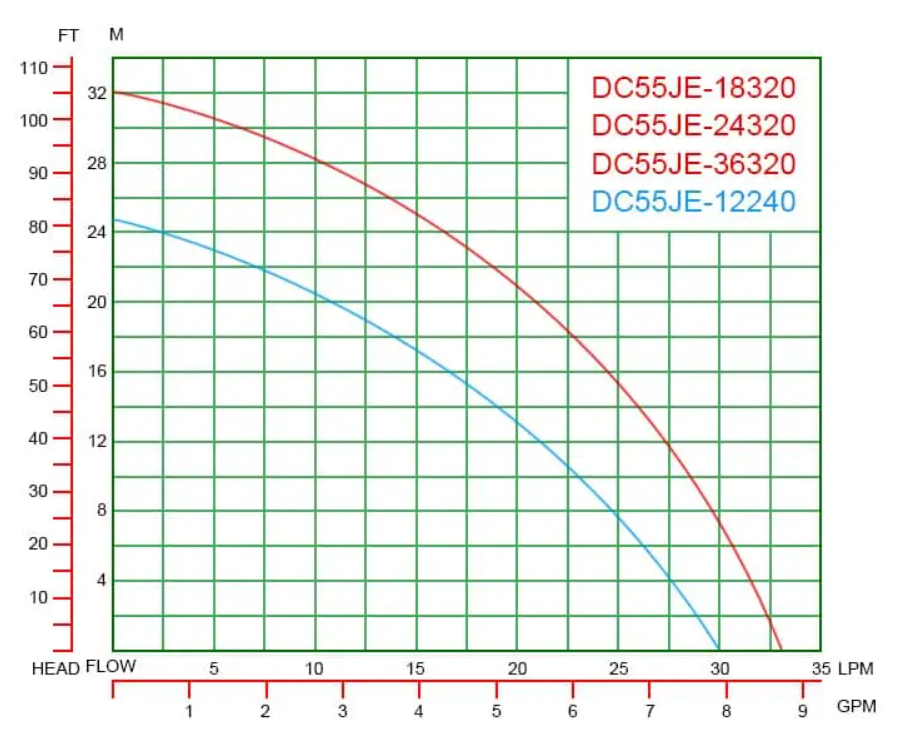
Fortunately, our previous pump turned out to be one of the best options I could find for a higher-pressure pump that could operate on our 24V system. To achieve our pressure drop requirements, I placed 3 of the pumps in series around the loop.
For the next iteration of the cooling loop, I would investigate parallel cooling configurations for the motors and inverters to reduce overall pressure drop and provide more balanced cooling across components. This would also put less strain on the car’s LV system, which was a major problem. For this year’s car, however, time constraints and limited testing led me to choose the more reliable option of a fully series loop, although this came at the cost of a higher pressure drop.
Inverter Pressure Drop Testing
Pump Curve
Implementation
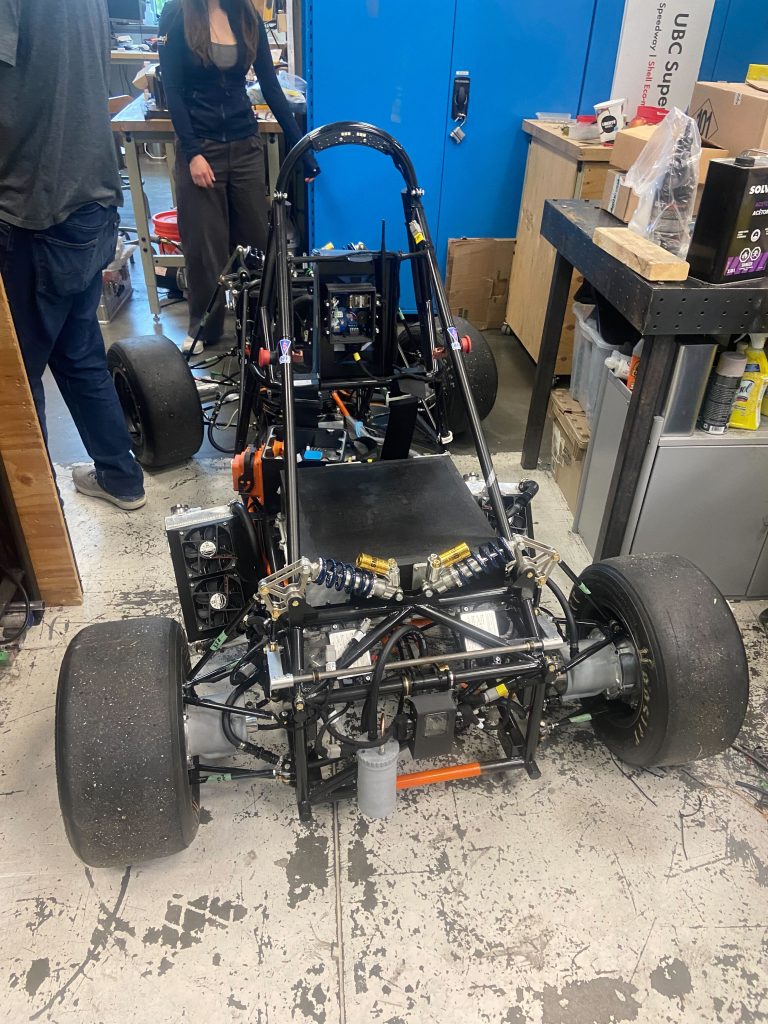
Below shows the rough layout of the cooling loop, with tubes spanning the length of the car to reach the front and rear motors, plus the inverters. Side-mounted radiators and pumps were ideal for packaging and pressure distribution through the system.
Contact
Please feel free to contact me through the following links!